9.4.7. Modelling of common cause failure#
In order to quantitatively assess the influence of common cause failure (CCF) on the system reliability several methods exist, for example [BR_SYS_14]:
Basic Parameter model - Uses direct probability of the common cause failure event.
Beta factor model - Estimates the percentage of CCF from total failure rate, the ratio of the common cause failure rate to the total rate is the beta factor. The Beta factor model is used for redundancies with two elements.
Multiple greek letter model - Is used for systems with higher level of redundancy or k-out of-n logic. The multiple Greek letter model includes parameters for the conditional probabilities that the N+1-th subsystem fails given that \(N\) identical subsystems have already failed.
Alpha factor model - All possible combinations of multiple failure events of k-out of-n subsystem are explicitly included. The factor \(\alpha_{k}\left( n \right)\) is the fraction of the total failure rate due to any \(k\) out of \(n\) failure.
Shock model – Assumes that common cause failure results from external events or shocks that occur with an average rate.
In the following, the contributing factors to common cause failures are explained, see Section 9.4.7.1. The quantitative assessment of common cause failures will be explained using the example of the basic parameter model, see Section 9.4.7.2, and the beta-factor model, see Section 9.4.7.3.
9.4.7.1. Contributing factors to common cause failure#
To quantify the possibility of CCF, the significant contributors that affect the coupling mechanisms will be reviewed.
The significant contributors are described by the following areas [BR_SYS_10]:
Separation / Segregation
Redundant component installed near each other can make the system susceptible to common cause fault resulting from physical interference between components. Such common cause failure can result from a failure of a single component when the physical effects are not limited to one component, e.g. fragments resulting from disintegration of pressure vessel could impact with other components. The more segregation of redundant components can be achieved, the less this factor influences CCF.
Note
For space applications, there are volume constrains which leads to limitations of separation and segregation of system components.
Diversity / Redundancy
The use of identical components in redundant system architecture bears the risk that an error that has been introduced during the development, manufacturing or installation leads to common cause failure of multiple redundant components. Development and production errors are in particular relevant for complex components, where exhaustive testing of all possible states is not possible to reveal the presence of an error. Similarity in the redundant architecture could be acceptable if components perform a limited number of functions and exhaustive testing can be performed. The use of different design principles, diverse hardware, diverse software or distinctly different design groups during the development reduces the susceptibility of a system to CCF resulting from a lack of diversity.
Complexity / Maturity of design / experience
A complex design with many components makes discovering coupling factors more difficult. Errors made during the design and development of systems have traditionally been detected and corrected by exhaustive tests conducted on the system and its components, by direct inspection, and by other direct verification methods capable of completely characterizing the performance of the system. These direct techniques can still be appropriate to reveal coupling factors for simple systems which perform a limited number of functions.
For complex systems, where testing of all conditions is practically impossible a stringent development process is needed to minimize development errors. That means development assurance is mandatory which includes bidirectional traceability from requirement to design and tests, design review with defined pass/fail criteria, a change process to document changes to definition and requirements during the development.
Use of assessments / Analysis and feedback data
The use of analysis methods, data tracking, and feedback from in-orbit data to improve the system can significantly reduce or mitigate the effect of CCF.
Procedures/ Human interface (e.g. testing/operation)
Human error can have a significant impact on CCF. Wrong procedure applied could result in loss of multiple redundant components.
Competence / Training
Creating an awareness of CCF and expertise in adequate design principles plays an important role in reducing CCF in development, design, manufacturing and operation.
Environmental control (e.g., temperature, humidity)
Redundant components are exposed to the same environmental conditions. Harsh environment condition, e.g. vibration, high or low temperature extremes, radiation etc., could provoke a common cause failure of multiple components.
To avoid that CCF restrict the achievable system reliability, redundancy should be coupled with technical diversity and physical separation. It is easier to prevent dependent failures by defeating coupling factors rather than by eliminating root causes. The potential defences were classified based on the coupling factors they prevent. Some specific approaches are:
Use diverse components in redundant sets,
Use separate locations for redundant components,
Connect the components in a redundant set to different supporting systems using diverse interconnection configurations.
9.4.7.2. Basic parameter model#
The basic parameter model is called a direct model because the probabilities of the different failure events are used directly. In the following, a simple redundant system with two identical components in parallel is considered, in which at least one out of two is required to work. It is assumed that the total failure probability consists of both independent and CCF, as shown in Fig. 9.4.31. The probability that either one of the two components fails independently is \(Q_{I}\). The probability that both components fail together from a common cause is \(Q_{C}\). The system failure probability is obtained by [BR_SYS_14]
Equation
The direct basic parameter model requires estimating all possible failure event probabilities, which could be obtained from in-orbit return (IOR) data of common cause failures but also from expert knowledge and engineering judgement.
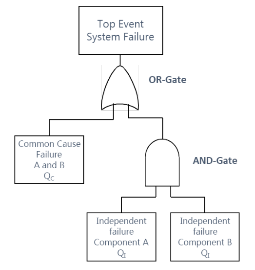
Fig. 9.4.31 System failure calculation including CCF – Basic parameter model#
9.4.7.3. Beta factor model#
For explanation of the beta factor model, also a system with two identical redundant components A and B is considered. The failure of one component will, with probability \(\beta\), cause all components to fail, and with probability \(1- \beta\), just involve the given channel. The total failure rate of a channel is obtained by [BR_SYS_10]:
Equation
Where,
\(\lambda_{I} = \left( 1 - \beta \right)\lambda_{T}\) denotes the failure rate of independent failure, and
\(\lambda_{C} = \beta\lambda_{T}\) denotes the failure rate of common cause failure.
The factor \(\beta\) is defined as the ratio of the failure rate due to common cause to the total failure rate.
Equation
In order to estimate the factor \(\beta\), the contributing factors for common cause failure is assessed.
9.4.7.4. Estimation of Common Cause Beta Factor#
With the categories of significant contributors to CCF shown in Section 9.4.7.1,the Common Cause Beta Factor (CCBF) can be estimated, starting with an assessment of each of the common cause susceptibility categories and for each, assigning a susceptibility score 1, 5 or 10 corresponding to the susceptibility, where 1 represents a low susceptibility to common cause failure in this category.
For example, a susceptibility score of 1 assigned to the category “diversity” would correspond to a system that consists of redundant component using different design concepts with no common hard or software, whereas a susceptibility score of 10 indicates a high susceptibility to CCF, for example redundancies consists of identical COTS ccomponents. Susceptibility, score 5, corresponds to medium susceptibility to common cause failure.
The sum over all categories provides the total Common Cause Score:
Equation
The next step is to assess the maximum common cause value MCCV. According to [BR_SYS_10] one of three possible values 10%, 20% or 30% should be selected for the MCCV based on experience of maximum common cause failure in the industry. For example, for an industry with a strong safety culture and established methods to analyse and mitigate common cause failure as it is the case for the space industry, the lowest value of MCCV is selected.
The beta factor is calculated as follows:
Equation
Where, \(\text{CCS}_{\max}\) denotes the maximum possible Common Cause Susceptibility Score, assigning 10 to each category.
As shown in the example in Table 9.4.15, the assigned Susceptibility Scores add up to a total Common Cause Susceptibility Score (CCS) of 32. With 7 categories, \(\text{CCS}_{\max}\) is 70. If the lowest value of 10% for \(\text{MCCV}\) is selected, the following \(\beta\) value is obtained from Eq. (9.4.91).
Equation
Category |
Susceptibility Score \(CCS_{i}\) |
|---|---|
Separation/segregation |
5 |
Diversity/ redundancy |
10 |
Complexity/maturity of design/experience |
5 |
Use of assessments/ analysis and feedback data |
1 |
Procedures/ human interface (e.g. maintenance/testing) |
1 |
Competence/ training/ safety culture |
5 |
Environmental testing |
5 |
Sum |
32 |