1.4. Reliability prediction taxonomy and handbook coverage#
1.4.1. Project phases and reliability in time#
The following paragraphs give a brief introduction to the project life cycle and to the different phases describing an item’s reliability over time. These concepts are needed to understand the taxonomy and for the reliability prediction process discussed in this handbook.
1.4.1.1. Project life cycle and space mission phases#
Space projects are typically divided in seven life cycle phases from 0 to F, as defined in Table 1.4.1 (cf [BR_METHODO_1]).
Project life cycle phases |
Satellites, space probes, crewed vehicles and satellites constellation |
Launchers |
|---|---|---|
Phase 0 – Mission analysis / needs identification |
Specification and Design |
Specification and Design |
Phase A – Feasibility |
Specification and Design |
Specification and Design |
Phase B – Preliminary Definition |
Specification and Design |
Specification and Design |
Phase C – Detailed Definition |
Specification and Design |
Specification and Design |
Phase D |
Qualification and production: |
Qualification: |
Phase E |
Utilization: |
Launch: |
Phase F – Disposal |
Deorbiting / Reorbiting / Passivation |
Deorbiting / Passivation |
Note 1
This table corresponds to typical mission phases. In case of pioneering missions, this should be adapted in consequence.
1.4.1.1.1. Satellites, space probes, crewed vehicles and satellites constellations#
The production and verification of the actual flight item takes place in phase D, followed by its launch and utilization in Phase E and the disposal at end of life in phase F. The duration of the mission is determined by the specified lifetime, counting from launch to end-of-life (disposal) of a spacecraft; sometimes the disposal phase is included to consider deorbiting/reorbiting success calculations. Possible lifetime extensions increase the duration of operations in-orbit.
In addition, information about mission phases prior to launch can need to be considered as an input for reliability prediction, e.g. to consider design and manufacturing process contributions, or to account for stresses experienced during acceptance testing.
1.4.1.1.2. Launchers#
The development and qualification of launchers include generally production of qualification models and first flight model. Phase C and phase D are linked for launcher development. Flight qualification is typically aligned with the first launch. Phase E encompasses production of operational launchers, ground operations before launch, and launch until payload separation. These actions mark the transition to operational deployment of payloads. Finally, Phase F corresponds to the end-of-life phase, during which launcher orbital stage carries out deorbiting operations.
From a practical point of view, launcher end-of-life operations are part of the mission timeline and they are fixed before launch. Consequence is that phase F, which is disposal, can also be considered as a subphase of phase E.
1.4.1.2. Reliability as a function of time#
Reliability generally varies as a function of time, although for some items it is more appropriate to consider reliability as a function of (or conditional on) demand, e.g. constant probability of failure for one shot items, stress-strength approach for shock loading. Nevertheless, from a system level perspective, these models can also be transformed to a time scale by making predictions on the occurrence of the relevant stresses and demands during the mission. At part-level, time dependent reliability is often explained with the well-known bathtub curve, as illustrated in Fig. 1.4.1.
The curve is divided in three phases:
In the initial phase, production errors and workmanship defects are a significant source of failure. When a component has survived a certain time, it implies that such birth defects are not present and consequently the reliability increases.
At the end of a component’s useful life, ageing and degradation failures lead to an increasing failure rate.
Between these two phases, no single wear-out mechanism is preponderant with regard to the failure rate of many parts (e.g. most EEE components). For these parts, in given use conditions, failure rate is low with little variation. A constant failure rate is a good approximation for reliability prediction during useful life. For other parts (e.g. mechanical ones), such a steady-state phase cannot be observed, and the failure rate is slowly increasing already during the useful life.
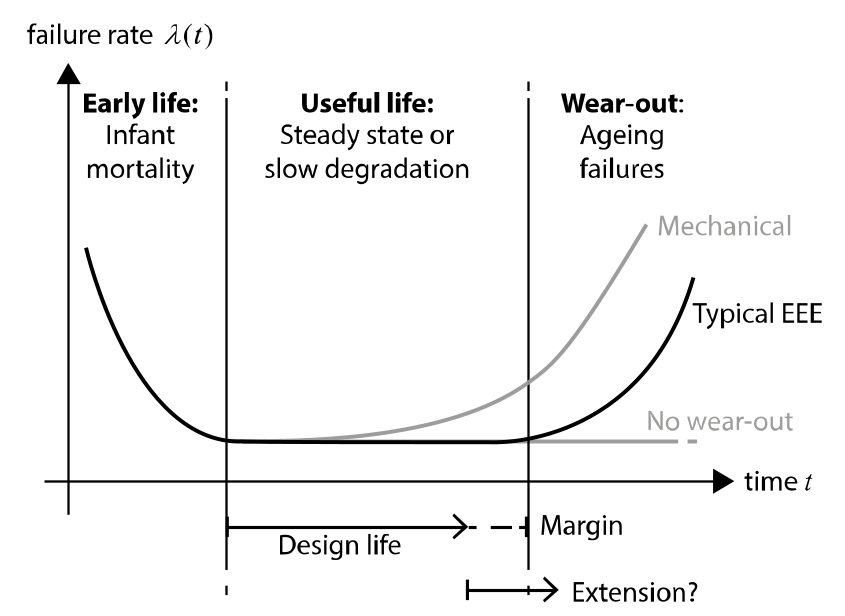
Fig. 1.4.1 The bathtub curve - failure rates as a function of time.#
To design a reliable product, all three phases illustrated in Fig. 1.4.1 need to be understood. However, this does not necessarily mean that the whole life cycle should be modelled in a reliability prediction context.
Early life failures are avoided with the aid of screening, testing and quality control. Assuming that these processes are effective, only components that have survived the infant mortality period will be used in the final product. It is thus justified, to neglect early life failures during reliability prediction, at least those due to component level defects. Non-part related systematic failures, resulting from system level design or manufacturing errors, can show a similar pattern and can be considered in the prediction using non-constant failure rates.
Degradation failures are considered during the design of a space system, e.g. by selecting suitable components or materials for the design lifetime and conditions of use. The objective is to ensure that all components remain within their useful life during the specified lifetime of the system; typically, a margin is considered to account for variability and uncertainties in the prediction of the component’s life expectation.
Modelling degradation effects, requiring a departure from the constant failure rate assumption, becomes relevant for items that exhibit an increasing failure rate already during the design lifetime (safe life qualification not possible, or not fully effective), or more broadly in the case of a lifetime extension for satellites, see Section 1.5.3.2.6 for details.
1.4.2. Classification of space systems and spacecraft elements#
The following paragraphs give some information about the classification of space systems, the levels of assembly and spacecraft elements.
1.4.2.1. Space product classification and handbook scope#
In space applications, reliability predictions need to consider different kinds of products with completely different attributes, e.g. related to the physical environment, the use conditions or the possibilities to repair a system once operations have started.
The handbook scope is limited to reliability predictions for systems that operate in space, e.g. spacecrafts. The following types of spacecrafts can be considered:
Satellite: uncrewed spacecraft in Earth orbit,
Space probe: spacecraft leaving earth orbit to explore further into outer space,
Satellites constellation, from two to hundreds or thousands of satellites,
Crewed vehicles and experiments or modules installed on space stations,
Launchers.
Finally, it should be noted that the handbook generally assumes a level of quality assurance as per ECSS standards for spacecrafts manufactured by major satellite prime contractors. The methodology and methods can of course be used also in other applications such as microsatellites or for “new space” applications. However, the models, background data and underlying assumptions cannot be fully applicable, especially when dealing with process and quality related contributions to unreliability, e.g. for reliability prediction of EEE components and assemblies Section 3 or when modelling systematic failures based on IOR (Section 9).
1.4.2.2. Levels of assembly from part to system#
For the purpose of this handbook, a system is considered in the generic sense and can be defined at any level as a set of components or functions that are interrelated or interact to achieve a specified objective.
Note 2
The lowest level of a system is an elementary part (or component).
For a more specific description of the level of assembly considered, the following levels can be distinguished (in the case of a spacecraft considered as the highest level of assembly):
Constellation level (system of systems),
Spacecraft level (only functional),
Interfaces level (electrical, mechanical or physical),
Equipment/Unit level (EEE, mechanical or miscellaneous),
Part/Component level (EEE, mechanical or miscellaneous).
For the constellation level, the spacecraft level and the interfaces level (dealing with the boundaries where different products interact) are considered in the frame of system level reliability prediction. For the equipment and component level, three technical domains are distinguished in this handbook, as outlined in Section 1.4.2.3 below.
The methods and models provided for these levels focus on elementary reliability prediction and can need to be combined with general system level models for equipment level reliability prediction (i.e. considering the equipment as a system of elementary parts). Additional levels (intermediate or beyond) can be considered as required by the analysis.
1.4.2.3. Spacecraft elements and technical domains#
At each level of assembly, different types of elements can be used as part of the overall system. This handbook distinguishes three types of hardware elements or technical domains (as defined in Part 7 – Glossary of this handbook):
EEE component
A EEE component performs an electrical, electronic or electromechanical function. At equipment level, an electrical unit is considered as a set of EEE parts assembled in a single package with structure, boards, wires and connectors to support the specified functions.
Mechanical part
It is defined as a non-electronics part, i.e. a part that does not perform any EEE function. At equipment level, a mechanical unit (or mechanism) is assembled of mechanical parts and possibly some EEE components to support the specified functions. Also, structural elements are considered as mechanical items.
Miscellaneous item
Either parts or assemblies that can neither be classified as EEE or mechanical/units (e.g. due to their EEE-mechanical hybrids aspects or to their complexity).
At spacecraft level, elements from these three categories, which focus on the classification of hardware, will generally interact with software to perform the required functions. Software failures are discussed in the context of system level reliability prediction, as a subclass of (non-part related) systematic failures.
1.4.3. Classification of failures by root cause#
Typically, multiple root causes contribute to an undesired outcome, but it is generally possible to discriminate which cause is the dominant one. For the methodology, we will consider one main root cause for each failure addressed as the one being the most probable. The classification of failures is based on this main root cause.
The four classes of failure listed in Table 1.4.2 are defined to be mutually exclusive and exhaustive, i.e. each failure observed in orbit can be classified into one of these four categories.
In the following table, each category is briefly discussed to further clarify the classification.
Failure category |
Root cause |
Remarks |
|---|---|---|
Random failure (RF) |
• Unknown residual defect/weakness: |
Relevant for: |
Systematic failure (SF) |
• Design error |
Relevant for: |
Degradation failure (DEG) |
• Normal physical process → time/equivalent time |
Considered as systematic failure when failure occurs before the design lifetime |
Extrinsic failure (EX) |
For launchers, the local environmental conditions apply. |
Space environment phenomena inducing external failure causes. |
1.4.3.1. Random failures#
For this handbook’s purpose, random failures are defined as failures occurring at an unexpected time due to a residual internal part defect or weakness when submitted to normal operational stresses (as seen in Part 7 – Glossary).
The physical root cause (the defect) is either unknown or considered as one-off after investigation. Therefore, whereas the origin of systematic, degradation and extrinsic failures can be identified, the random failures represent the failures that can occur at a rate to be determined without understanding what triggered them. We can say that the root cause of random failures is unknown.
Obviously, every failure has a root cause, and at least in theory, we might be able to classify each random failure as either systematic, degradation or extrinsic. However, it is, not realistic to achieve this in practice nor is it required from a modelling perspective. Random failures are always part-related and mutually independent from one system to another.
Examples of random failures :
Capacitor short circuit without identified cause
Pyrotechnic device fails to ignite
1.4.3.2. Systematic failures#
Systematic failures are related in a deterministic way to a certain cause, which can only be eliminated by a modification of the design, the manufacturing process or the operational procedures (as seen in Part 7 – Glossary).
The root cause of systematic failures originates from a human error during the design phase (design error), during the manufacturing phase (manufacturing error) or during the operational phase (operations error).
“Systematic” means that the failure would occur if similar elements (with the same errors) are operated under identical circumstances. To give an example, in case of a design error at equipment level, both nominal and redundant channels are impacted in the same manner even though not necessarily at the same time and with an associated probability of occurrence. As a result, systematic failure occurrence can be affected by common cause effects and cannot be assumed to be independent as in the case of random failures. However, the degree of dependence between two systematic failures resulting from the same root cause depends on the case and can range from nearly independent e.g. manufacturing error on a single hardware element) to almost fully dependent (e.g. design error affecting identical equipment operating under the same conditions) in different settings.
Usually, systematic failures can be part-related (due to part design or manufacturing errors) or non-part related, i.e. the error can be introduced at higher than part level.
In the frame of this handbook, it is assumed that the occurrence of part-related systematic failures is effectively reduced by using space qualified components and by the processes in place, in case of an alert issued by the manufacturer. At this quality assurance level, part-related failures due to design or manufacturing errors can be assumed covered by the random failure rate. Therefore, the focus of systematic failure modelling in this handbook will be on the consideration of non-part related systematic failures.
Examples of systematic failures:
Gold pollution during the assembly of a EEE package (part level, manufacturing)
Poor lubricant choice leading to increased friction in a mechanism (equipment level, design)
Printed Circuit Board (PCB) cracked by the manufacturing tool (equipment level, manufacturing)
Wrong connection of a connector (interface level, manufacturing)
Underestimated Single Event Effect (SEE) flux prediction (spacecraft level, design)
Sign error in the command chain of a reaction wheel (spacecraft level, software coding)
Wrong procedure leading to send a dangerous command (spacecraft level, operations)
1.4.3.3. Degradation failures#
Degradation failures are irreversible failures resulting from progressive degradation of an item’s performances in time, due to calendar aging or due to operational and/or environmental stresses.
The root cause is a degradation process (modification of the design characteristics) at part-level.
Space system design aims at avoiding degradation failures by ensuring that limited lifetime items are “safe life” qualified, which means that these items are designed to withstand the design lifetime (with acceptable performances degradation) and qualified by tests, generally with a safety factor. Therefore, no failure due to degradation is expected before the end of the specified lifetime. Failures due to “early” degradation before this point are classified either as systematic in the case of a design or manufacturing error, or as random if an unknown residual part defect has accelerated the degradation process.
In case of a lifetime extension beyond the specified design life, the safe life qualification is no longer valid, and degradation failures can need to be considered in the prediction. The same holds true for technologies or items that already show (moderate) degradation during the normal design life, e.g. in the case of various mechanical parts. Reliability models used for these items need to consider increasing failure rates due to the non-negligible impact of internal degradation processes.
The different stresses that can lead to degradation failures are classified as follows:
Operations-related: Use in time, On/Off cycling, mechanical wear,
Environment-related: Thermal cycling, cumulated radiation, UV light, mono atomic oxygen.
To ensure mutually exclusive categories and as a matter of convention, failures resulting from degradation due to environmental effects are classified as degradation failures (not extrinsic) failures.
When modelling degradation, it is important to be clear about the definition of “failure”. The time dependent physical degradation of an item as such is not considered as a failure before a critical threshold is surpassed, leading either to a definitive failure at part level or to a failure at system level without part failure. An example for a definitive degradation failure would be, fracture of a mechanical part after successive crack growth due to cyclic loading. Whereas in the case of a battery discharge, failure due to calendar aging is better defined at system level by specifying a performance threshold for the battery capacity (Ah).
Examples of wear-out / degradation:
Progressive parameter drift at EEE part level due to cumulated radiation effects, displacement charge effects (Total Ionizing Dose (TID) / Total Non-Ionizing Dose - TNID)
Mechanical bearing failure due to lubricant wear leading to mechanism failure
Energy and/or power loss (below specified threshold) in batteries due to calendar ageing
1.4.3.4. Extrinsic failures#
Extrinsic failures are sudden failures induced by the environment on the spacecraft elements.
Note 3
As mentioned in Table 1.4.2, the extrinsic failures for launchers are due to the weather conditions around the launcher facilities. This will not be developed here. Only the space conditions leading to extrinsic failures on satellites, uncrewed/crewed vehicles and probes are addressed in this paragraph as these are the ones specific to space applications.
The root cause is the environment, imposing the following stresses:
Physical conditions (defined in the technical specification),
Vacuum: outgassing, cold welding, heat transfer
Thermal effects: solar radiation, solar albedo, Earth Outgoing Longwave radiation (OLR),
Geomagnetic field: depending on solar wind, solar activity,
Launch effects,
Mechanical vibration: vibrations during launch,
Shocks: e.g. pyro activation,
External particles,
Plasma: Electro Static Discharge (ESD),
Heavy ions, SEE: destructive, non-destructive,
*Micrometeoroid and Orbital Debris (MMOD) impacts,
Failures due to cumulated extrinsic effects are (by convention) classified as degradation failures, see Section 1.4.3.3 above. Thus, failures due to the following stresses only need to be considered when degradation predictions become relevant, e.g. to support decision-making on possible satellite lifetime extensions:
Degradation due to extrinsic effects
Single atomic oxygen
Radiations: ionizing / non ionizing
Ultra Violet (UV) light
Finally, failures due to extrinsic effects that were underestimated during the design are classified as systematic, as the root cause is a design error rather than the space environment alone.
Examples of extrinsic failures :
Destructive Single Event Effects (SEE) (e.g. Single Event Lath up (SEL) or Single Event Burnout (SEB))
Non-destructive SEE causing a non-detected corruption of data used in a system control loop
Outgassing of materials leading to contamination of optical devices
Debris impact causing failure critical components that are not protected by shielding
Fracture of a structural element due to launch vibrations or shock loads
1.4.4. Coverage of spacecraft elements and failures in this handbook#
The following paragraphs gives a brief overview on the coverage in terms of spacecraft elements and failure root causes provided in the handbook’s model parts Section 3, Section 5, Section 7 and Section 9.
1.4.4.1. Elements coverage#
To simplify the application of the handbook for users in practice, Section 3, Section 5 and Section 7 are structured based on the technical domains introduced in Section 1.4.2.3:
Section 3 for the modelling of EEE components and assemblies,
Section 5 for the modelling of mechanical and structural parts and assemblies,
Section 7 for the modelling of miscellaneous items,
Section 9 for system level considerations, independent of the technical domains.
In terms of levels, Section 3 to Section 7 focus on elementary reliability modelling for parts or low levels of assemblies (up to function/equipment level) in each technical domain, whereas the approaches discussed in Section 9 can be applied at any level to systems in the generic sense.
1.4.4.2. Root cause coverage#
For the coverage in terms of failure categories, the methodology has a clear focus on random failure modelling, leaving the consideration of other root causes to dedicated model extensions.
Note 4
The distinction between random, systematic, degradation and extrinsic failures is not always a clear-cut and can sometimes be a modelling choice, or a matter of definition, rather than resulting directly from the “nature” of the failures.
Section 3, Section 5 and Section 7, about respectively the EEE, mechanical and miscellaneous items, each provide information about the coverage in terms of root causes of failure.
A quick overview for all paragraphs is given in the following:
Random failures: Random failures are clearly a relevant input for the design of reliable systems. They are fully covered by the methodology provided in this handbook.
Systematic failures: The models provided in this handbook do not guarantee a complete coverage of all systematic failures for all spacecraft elements.
For EEE items, a certain coverage of systematic failures is achieved with the aid of process factors adapted to space applications.
For mechanical items, the methodology allows the consideration of failures due to minor design uncertainties and manufacturing variability. Gross errors require dedicated modelling at system level.
For miscellaneous items, the methodology allows the consideration of systematic failures from a simple statistical perspective, referring to the modelling at system level as well.
General considerations for systematic failure modelling are given in the system level chapter, including a statistical model based on IOR data.
Degradation failures: Also degradation failures are not completely covered by the models provided in this handbook:
For EEE items, the models provided generally assume constant failure rates during the useful life of a component, but a methodology for the separate consideration of degradation failures is proposed, in case an explicit degradation modelling is needed, e.g. in the context of a lifetime extension.
The methodology for mechanical reliability prediction includes an explicit consideration of relevant degradation failure mechanisms, which can be used to model premature failures before the end-of-life, as well as degradation failures during a potential lifetime extension.
For miscellaneous items, the methodology includes the consideration of degradation failures, modelled beyond the mission lifetime based on an increasing failure rate and with model parameters related to the lifetime qualification of the items.
System level considerations of degradation modelling can be found in the Section 9 of this handbook, including approaches for the combination of a constant failure rate for random failures with a separate degradation model implying increasing failure rates.
Extrinsic failures: Many of the environmental stresses considered for the definition of extrinsic failures are in fact part of the normal environment for a spacecraft and its components. Thus, some of them are considered as “stress contributors” for the random failure modelling. Others are assumed to be covered and effectively avoided by different design disciplines and excluded from the base methodology.
A dedicated discussion of extrinsic root causes by technical domain can be found in the EEE chapter, MEC chapter and MIS chapter of this handbook.